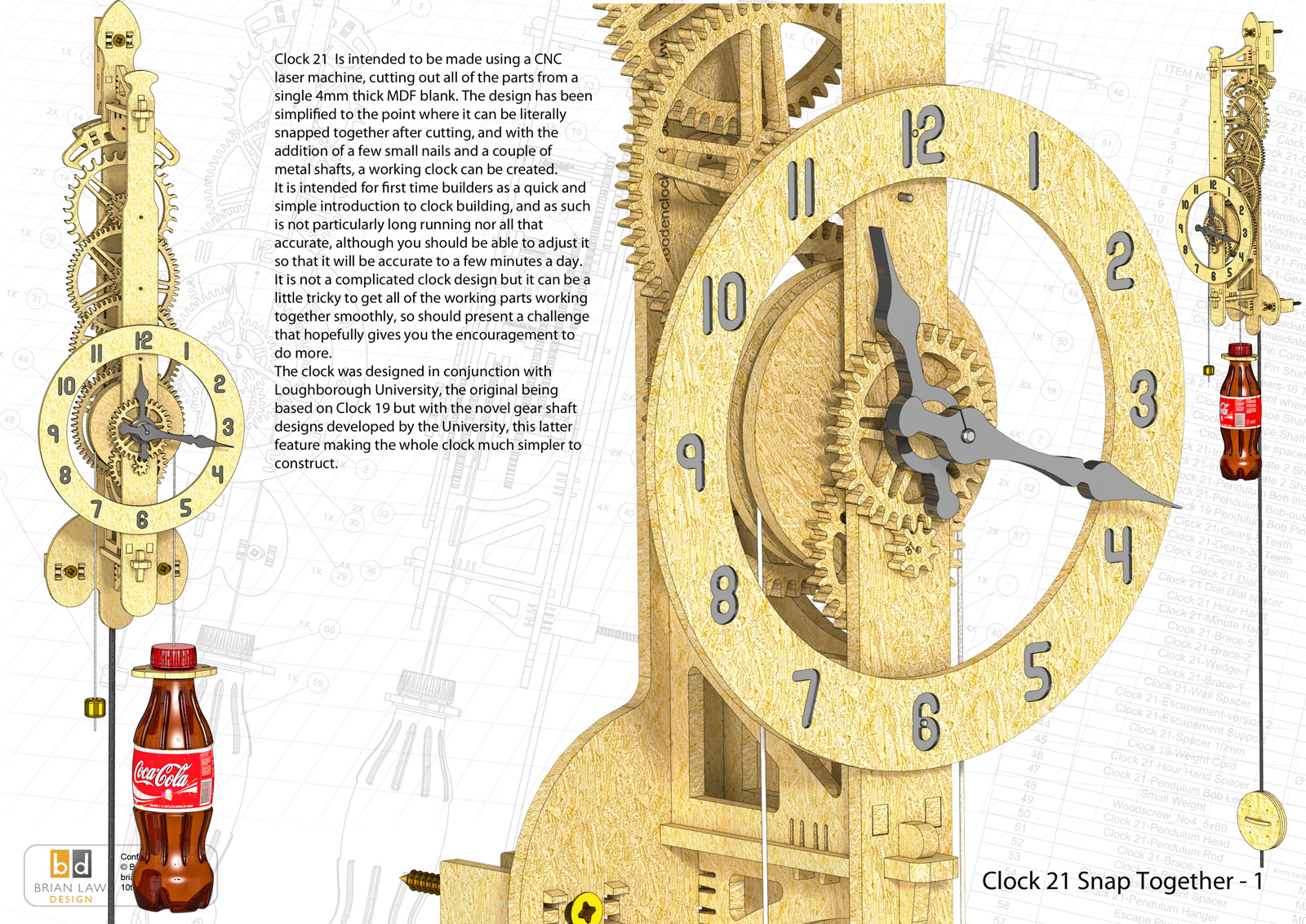
Clock 21 really is intended to be snapped together, it has been design be to be cut out from a single sheet of MDF 4 mm thick and 600 mm x 400 mm in size with a CNC laser or CNC router.
The design has been a collaboration with Loughborough University and Woodenclocks to produce a clock design suitable for use in STEM projects within schools to encourage an interest in Engineering.
The starting requirement was for a clock that could be built simply and within a very short time frame so that it could fit into a schools timetable. It also required that it could be made with limited resources and at a minimum cost. The University had already done some work with an escapement mechanism which used Laser cut 4 mm MDF for the parts and a novel shaft design that could be snapped together.
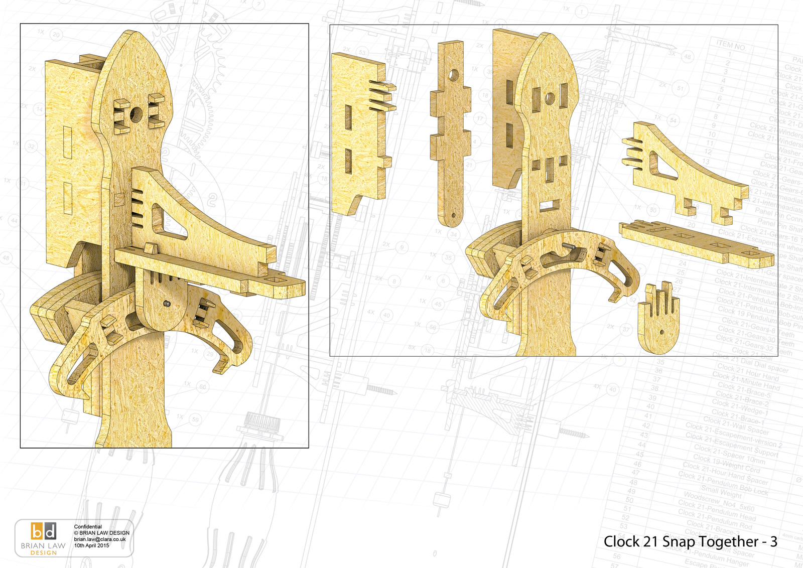
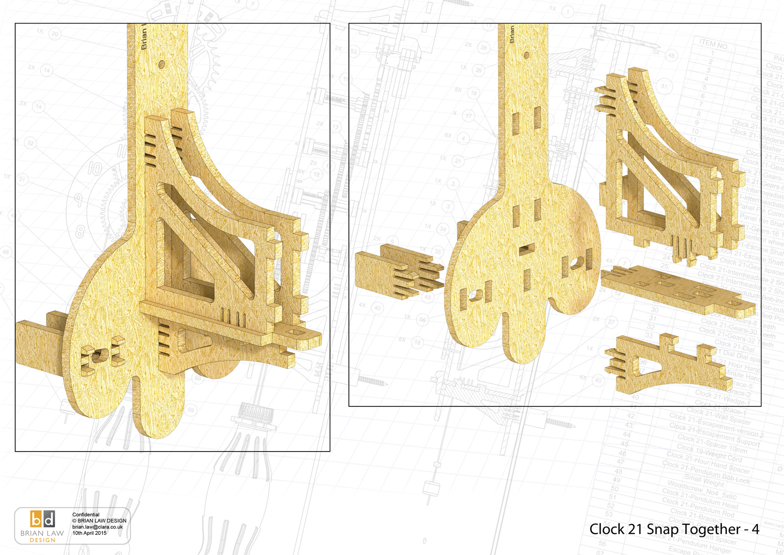
Woodenclocks contribution was to redesign Clock so that it could be made from 4 mm MDF, and simplify the frame construction so that the whole clock could be snapped together. To ensure that the clock would be simple to assemble several novel features have been incorporated.
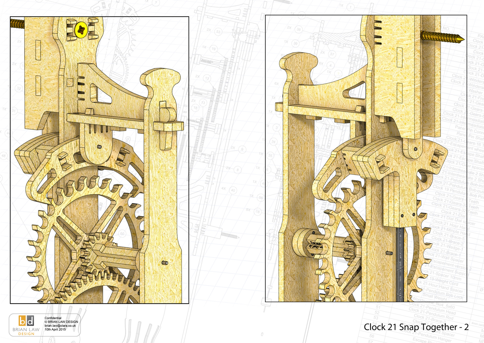
1 – Firstly the snap together design required quite a few iterations of the clips used to hold the parts together and now the finished clock is quite rigid despite being made from 4 mm MDF. This rigidity will depend to a large part to the setting on your CNC laser, if the fit is too tight the parts won’t go together and if too loose then some parts will move during the operation of the clock, and stop it working. To ensure that doesn’t happen its probably best for you to take a couple of the snapping parts and do some test runs with your settings for the laser offsets. The setting we used are given in the instructions. To be sure nothing important moves its best to glue all the upper brackets that fit to the back frame in place.
2 – The weight used for this clock is unusual in that it is a simple 500 cc drinks bottle with a holder secured in place by the bottle cap. This CNC cut holder has notches so that a loop of cord can be easily attached and detached if needed.
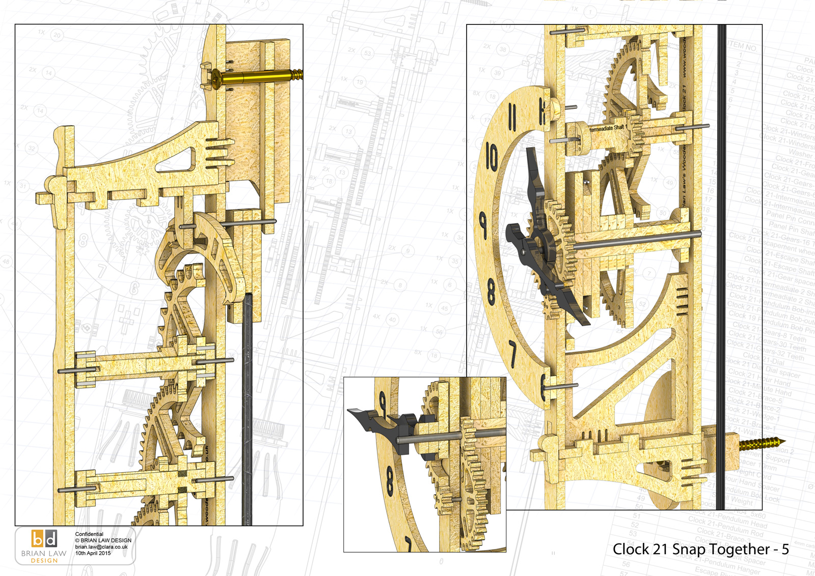
3 – The lock used for holding the Pendulum on the shaft is again cut from the MDF sheet and has a slight spring fit onto the Pendulum Rod to hold it in place, simply push on this lock to ease its fit and allow the Pendulum Bob to be moved up or down to speed up or slow down the clock.
4 – Finally the simple wedges that lock the front frame in place
Its intended use for schools should not deflect from the fact that any one with a CNC laser or CNC router can use this design to build the clock. The current design can be modified endlessly by yourself to build something quite unique , you can change the form of the parts and the materials and the finishes used to create something quite different.
You only need to keep the gear teeth, diameters and the gear spacing the same as this one, the rest is up to you.
If you are looking for a simple design for a first time project that can be completed in a couple of days, then this is it.
You can view the Detail drawings of the clock and the renders showing in detail the construction of the clock. The free files are restricted and are not suitable for actually making the clock with but all the drawings and renders along with the DXF and DWG files for using with CNC machining can be purchased from the download page.
Update! The files for clock 21 have been updated to include cutting profiles for use with a CNC router. It is worth noting that the original laser cut design actually sealed the cut faces whilst cutting. If you are going to CNC router cut the parts, I found it best to clean up the edges with fine sandpaper and the use Liquid Super glue to seal the teeth and the pallets.
DXF, DWG 2D files, and the IGS and STP files that can be used with your Laser or CNC machine can be downloaded here for $26. You also get the unrestricted version of the PDF files that can be printed at full size.
Drawings for this clock in PDF format can be downloaded here. These free files are restricted so that you can only view them on screen but not print them. Clicking here will download the PDF file directly to your browser, may take a few moments so please be patient.
To view
the assembly instructions for the clock
click here.
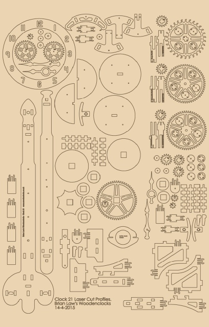
A sample from the DXF/DWG files is shown here. The actual files purchased above are included on one large sheet so that they may be directly loaded into your CAM program.
To print only a single item of the drawing to scale using Adobe Acrobat Reader, do the following:
Go to Edit, then click on Take a snapshot, move the cursor to the top left of the item you want to print and hold down the left mouse button whilst you drag a box around the item. The inside of the box turns blue and you can now go to File and then click on Print. This brings up the print dialogue, make sure Selected graphic is selected and that the Page scaling is set to None and the click on OK. As long as your printer is connected you will have printed the item at size. Do this for each item you want to cut out.