There are only three methods of creating the gear teeth, I have tried two of the methods, the first involves the use of a Bandsaw the second a CNC milling machine and the third method involves the use of a laser. The latter being eminently preferable to the first.
 trying to cut through. The thicker the wood is, the more power that you need and this puts more heat into the wood as well. Also, some woods have more resin and oils in them that come out in the laser process. We send out a wood sample that we engrave and cut without any charring on the edge. Because of the variables, it is hard to give you specific tips/hints. Usually you want to cut on wood with a low PPI rate
(PPI = Pulses Per Inch). This controls how much heat is being used to cut into the wood.”
The sample shown opposite was supplied by Universal laser systems and is about 12 mm thick. It was cut from maple using their X2-600, 100 watt system and took 2:46 seconds to cut. The edge is dark but does not leave a residue on your fingers when it is handled.
Doug McIntyre who uses a smaller ULS machine wrote to me concerning correspondence on the Laser newsgroup:
“I purchased a ULS laser a few months ago for a new venture and would agree with the replies. The laser can cut various woods with perfect accuracy but is limited by power of the laser and hardness of the wood. In reality it is a 2 dimensional machine. I noted that one of your gear wheels was ‘dished’ to a concave. This is possible but very time consuming on a laser as it has to be burned out in increments. However, it is ideal for cutting the teeth and also the hole in the middle subject to thickness and the power of the laser.
A bonus with this machine is that it can both cut and engrave in one operation i.e., it is feasible to cut a wheel and decorate it as well. As a matter of coincidence, I was experimenting on Pine, Sycamore and Mahogany yesterday to find out the cutting depths. I never finished, but 1/4″ is almost the limit on my machine (25 watts, which is about the standard for general engraving/cutting in the promotional gifts engraving field). The price of the machine escalates considerably at higher powers.”
I think from this it is feasible to use a laser to cut the parts for a clock, and the results would be extremely accurate. The slight charring of the sample sent to me would be relatively easy to clean up and the work involved more than offset by the speed of the laser.
It would however appear that the current parts at 10 mm thick may be too much for the standard laser of about 30 watts power. It may be possible in the future to design a smaller clock with gear thickness around 5 mm to enable full use of the lower powered laser.
trying to cut through. The thicker the wood is, the more power that you need and this puts more heat into the wood as well. Also, some woods have more resin and oils in them that come out in the laser process. We send out a wood sample that we engrave and cut without any charring on the edge. Because of the variables, it is hard to give you specific tips/hints. Usually you want to cut on wood with a low PPI rate
(PPI = Pulses Per Inch). This controls how much heat is being used to cut into the wood.”
The sample shown opposite was supplied by Universal laser systems and is about 12 mm thick. It was cut from maple using their X2-600, 100 watt system and took 2:46 seconds to cut. The edge is dark but does not leave a residue on your fingers when it is handled.
Doug McIntyre who uses a smaller ULS machine wrote to me concerning correspondence on the Laser newsgroup:
“I purchased a ULS laser a few months ago for a new venture and would agree with the replies. The laser can cut various woods with perfect accuracy but is limited by power of the laser and hardness of the wood. In reality it is a 2 dimensional machine. I noted that one of your gear wheels was ‘dished’ to a concave. This is possible but very time consuming on a laser as it has to be burned out in increments. However, it is ideal for cutting the teeth and also the hole in the middle subject to thickness and the power of the laser.
A bonus with this machine is that it can both cut and engrave in one operation i.e., it is feasible to cut a wheel and decorate it as well. As a matter of coincidence, I was experimenting on Pine, Sycamore and Mahogany yesterday to find out the cutting depths. I never finished, but 1/4″ is almost the limit on my machine (25 watts, which is about the standard for general engraving/cutting in the promotional gifts engraving field). The price of the machine escalates considerably at higher powers.”
I think from this it is feasible to use a laser to cut the parts for a clock, and the results would be extremely accurate. The slight charring of the sample sent to me would be relatively easy to clean up and the work involved more than offset by the speed of the laser.
It would however appear that the current parts at 10 mm thick may be too much for the standard laser of about 30 watts power. It may be possible in the future to design a smaller clock with gear thickness around 5 mm to enable full use of the lower powered laser.
Bandsaw
For this route to be successful great care needs to be taken to start with an exactly scaled plan that can be bonded to the surface of the timber to be used for the gear with a low tack adhesive. Once the plan has been applied to the timber you can begin by cutting around the profile with the Bandsaw taking care to leave a small amount around the profile for final Linishing. The next step is to replace the Bandsaw blade with a narrow Linishing belt (these should be available from your blade supplier), and with the assistance of an appropriately shaped support block held behind the Linishing belt, the teeth can be linished to the final profile. Once the profile is finished you will need to mark carefully out and drill the centre hole. This is really best done by mounting the gear on a faceplate in a lathe and centring it prior to drilling. The importance of getting the hole central cannot be emphasised enough as it is crucial to the proper running of the clock.CNC milling
If you have access to CNC milling then the whole process of creating the gear teeth is so much more accurate and will save hours later, by avoiding the need to tweak the tooth profiles while assembling the clock. The DXF file necessary for CNC machining of the clock profiles is available for download on this site. A $20 charge is made for these files.Laser cutting
This is similar to CNC routing but uses a laser beam to cut. I contacted Michael Ireland at Universal Laser Inc to see f it was possible, as I was concerned that the power needed to cut through a 10 mm section of wood would badly char the surface. This was Michael response: “The laser can be used to cut wood. Typically you do get a brownish edge colouring. This can be controlled to a certain extent. Much depends on the type of wood and the thickness that you are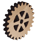 trying to cut through. The thicker the wood is, the more power that you need and this puts more heat into the wood as well. Also, some woods have more resin and oils in them that come out in the laser process. We send out a wood sample that we engrave and cut without any charring on the edge. Because of the variables, it is hard to give you specific tips/hints. Usually you want to cut on wood with a low PPI rate
(PPI = Pulses Per Inch). This controls how much heat is being used to cut into the wood.”
The sample shown opposite was supplied by Universal laser systems and is about 12 mm thick. It was cut from maple using their X2-600, 100 watt system and took 2:46 seconds to cut. The edge is dark but does not leave a residue on your fingers when it is handled.
Doug McIntyre who uses a smaller ULS machine wrote to me concerning correspondence on the Laser newsgroup:
“I purchased a ULS laser a few months ago for a new venture and would agree with the replies. The laser can cut various woods with perfect accuracy but is limited by power of the laser and hardness of the wood. In reality it is a 2 dimensional machine. I noted that one of your gear wheels was ‘dished’ to a concave. This is possible but very time consuming on a laser as it has to be burned out in increments. However, it is ideal for cutting the teeth and also the hole in the middle subject to thickness and the power of the laser.
A bonus with this machine is that it can both cut and engrave in one operation i.e., it is feasible to cut a wheel and decorate it as well. As a matter of coincidence, I was experimenting on Pine, Sycamore and Mahogany yesterday to find out the cutting depths. I never finished, but 1/4″ is almost the limit on my machine (25 watts, which is about the standard for general engraving/cutting in the promotional gifts engraving field). The price of the machine escalates considerably at higher powers.”
I think from this it is feasible to use a laser to cut the parts for a clock, and the results would be extremely accurate. The slight charring of the sample sent to me would be relatively easy to clean up and the work involved more than offset by the speed of the laser.
It would however appear that the current parts at 10 mm thick may be too much for the standard laser of about 30 watts power. It may be possible in the future to design a smaller clock with gear thickness around 5 mm to enable full use of the lower powered laser.
trying to cut through. The thicker the wood is, the more power that you need and this puts more heat into the wood as well. Also, some woods have more resin and oils in them that come out in the laser process. We send out a wood sample that we engrave and cut without any charring on the edge. Because of the variables, it is hard to give you specific tips/hints. Usually you want to cut on wood with a low PPI rate
(PPI = Pulses Per Inch). This controls how much heat is being used to cut into the wood.”
The sample shown opposite was supplied by Universal laser systems and is about 12 mm thick. It was cut from maple using their X2-600, 100 watt system and took 2:46 seconds to cut. The edge is dark but does not leave a residue on your fingers when it is handled.
Doug McIntyre who uses a smaller ULS machine wrote to me concerning correspondence on the Laser newsgroup:
“I purchased a ULS laser a few months ago for a new venture and would agree with the replies. The laser can cut various woods with perfect accuracy but is limited by power of the laser and hardness of the wood. In reality it is a 2 dimensional machine. I noted that one of your gear wheels was ‘dished’ to a concave. This is possible but very time consuming on a laser as it has to be burned out in increments. However, it is ideal for cutting the teeth and also the hole in the middle subject to thickness and the power of the laser.
A bonus with this machine is that it can both cut and engrave in one operation i.e., it is feasible to cut a wheel and decorate it as well. As a matter of coincidence, I was experimenting on Pine, Sycamore and Mahogany yesterday to find out the cutting depths. I never finished, but 1/4″ is almost the limit on my machine (25 watts, which is about the standard for general engraving/cutting in the promotional gifts engraving field). The price of the machine escalates considerably at higher powers.”
I think from this it is feasible to use a laser to cut the parts for a clock, and the results would be extremely accurate. The slight charring of the sample sent to me would be relatively easy to clean up and the work involved more than offset by the speed of the laser.
It would however appear that the current parts at 10 mm thick may be too much for the standard laser of about 30 watts power. It may be possible in the future to design a smaller clock with gear thickness around 5 mm to enable full use of the lower powered laser.