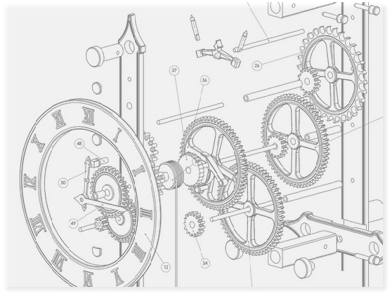
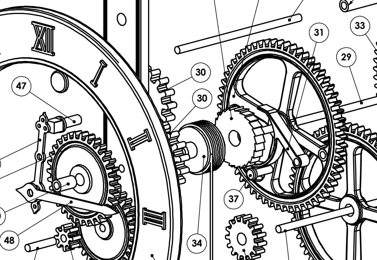
These are sample sheets from the drawings that can be downloaded. The drawings have been stored in a PDF file which is a vector format file, that can be printed out at full size for use in cutting parts of the clock.
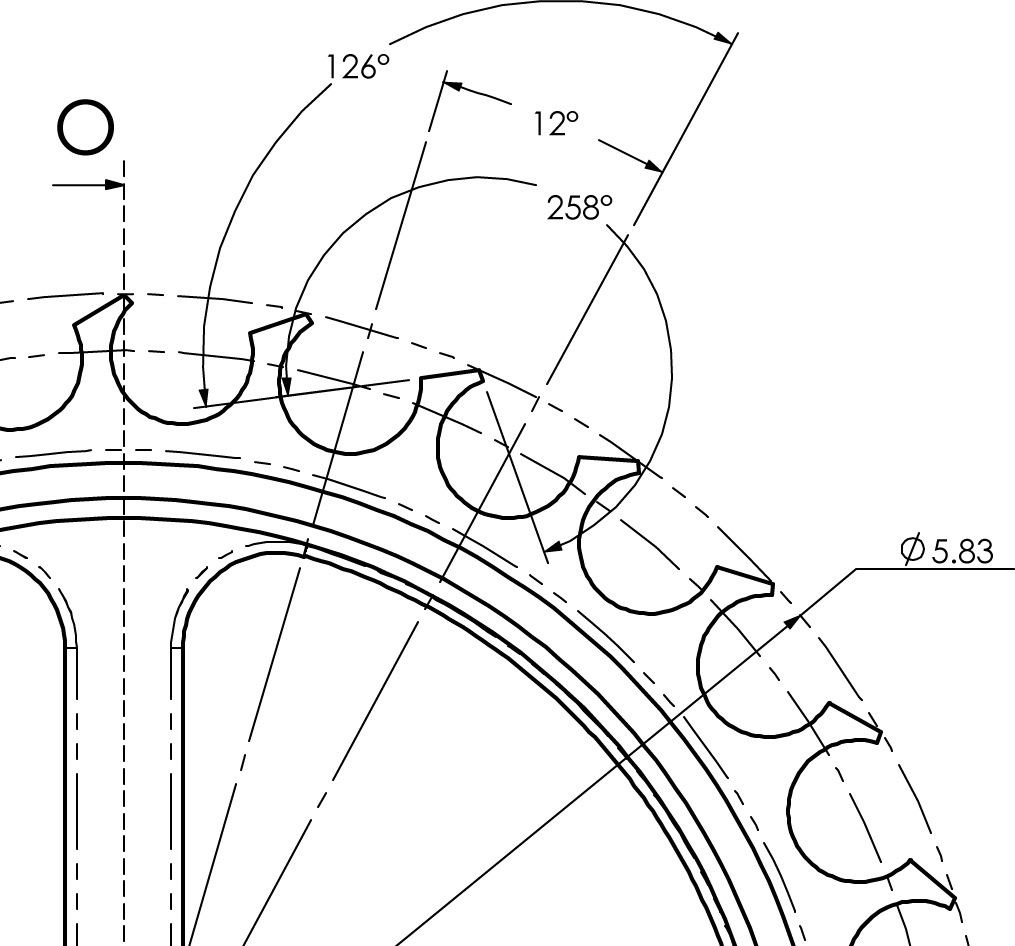
The drawings have dimensions for all the important features of the design. One of the most important dimensions to get right when building a clock is the centre distances between the holes for the shafts, errors here will cause untold hours of correctional work later.
For other features it is less important to achieve that same high degree of accuracy, but none the less it is important for the ease of build and overall appearance, that these dimensions be adhered to, examples of this, are the positioning of the gears on the shafts, a few millimetres either way will not stop the clock working , but it will have a detrimental effect on the appearance.
There are some features that have not been dimensioned at all, These features are really left to your own interpretation, you can of course copy the details from the plans, but you can also go your own way to bring something that is exclusively your own to the finished design.
The detailing of the gear teeth is a special case, because of the way they will be made. It is assumed that you will either use the plans directly by sticking them to the surface of the wood to cut around, or they will be machined by CNC methods either routing or Laser. Either route does not directly require dimensions for each tooth but should you wish to know the underlying geometry used the chart below will help.
Details on how the assembly fits together and the type of fits to make between the various parts, are given on the last sheet of the drawings for clocks 1,2,4,5 along with notes on special features of the assembly
When used in combination with the high resolution rendered images shown on the clocks pages it is possible to obtain a full understanding of how the clock works and what makes it tick.
Escapement
The animation shown above is a representation of the escapement used on clocks 1 & 2. Click on the small image to bring up the animation.
What it really shows is how important it is to be accurate in the construction of the parts that comprise the escapement, as movement of the pallets into the spaces between the teeth is a very tight fit indeed.