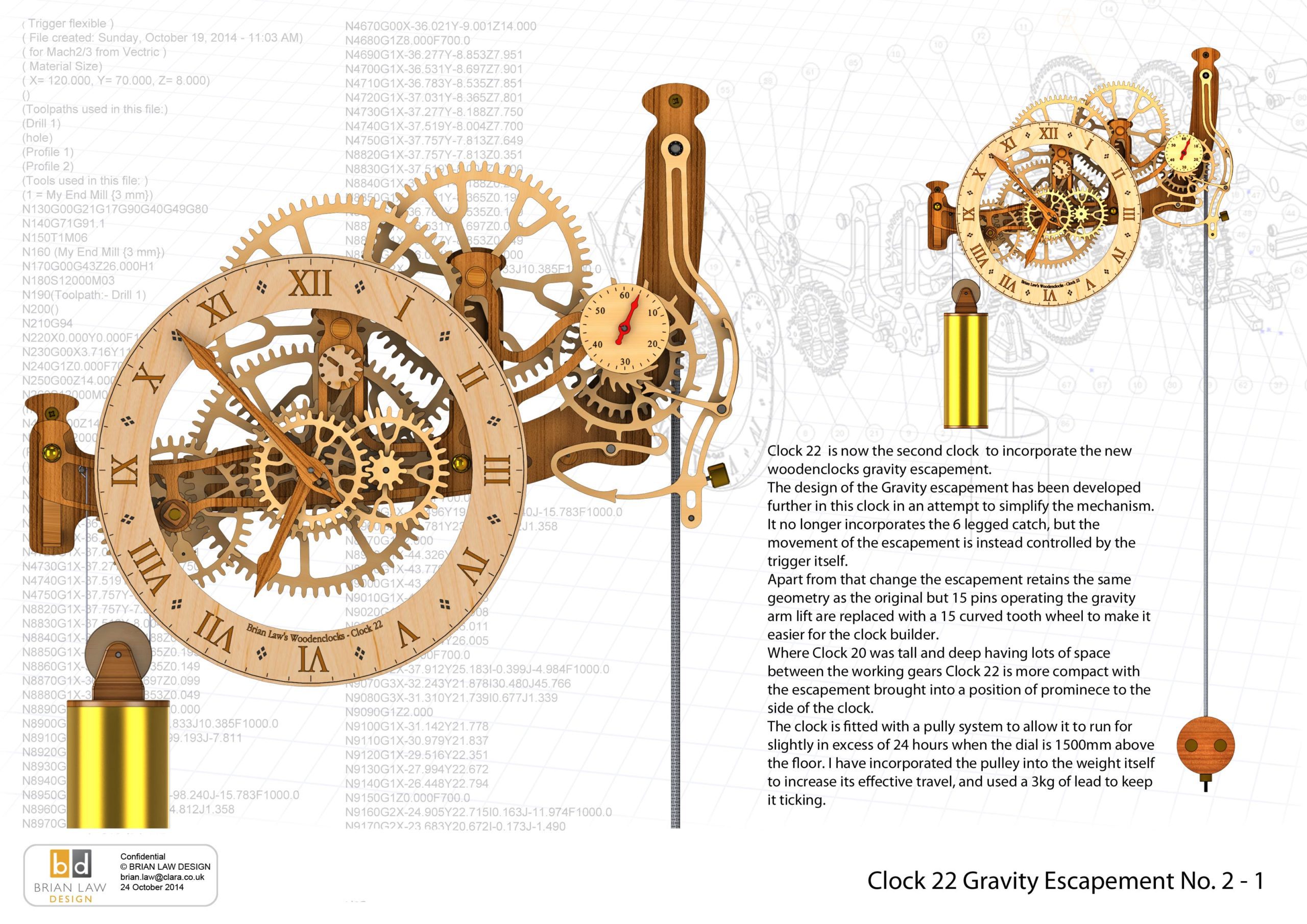
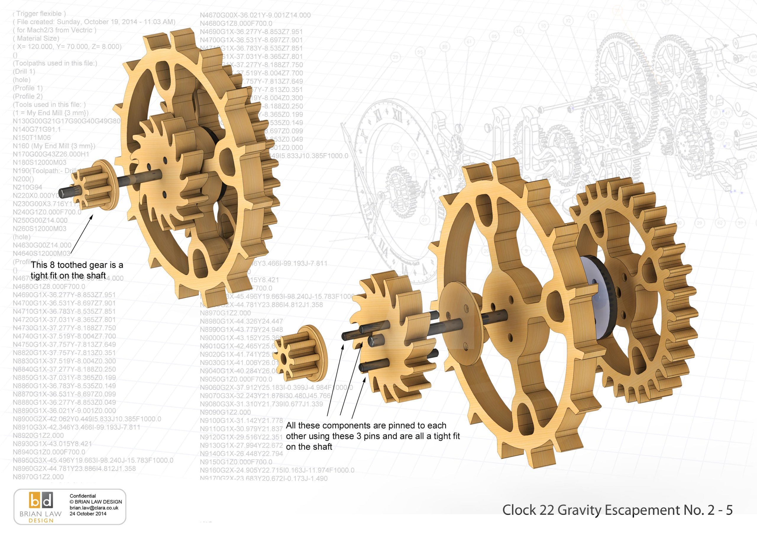
Clock 22 again incorporates the Woodenclocks Gravity Escapement. This time the design has been simplified, by removing the 6 legged Catch and engaging the Trigger directly with the escape wheel. I originally thought that the six legged catch brought an added layer of safety to the design as it always stayed engaged with the escapement, but in truth it only needed the trigger to miss to allow the clock to jump a beat so allowing the trigger to work directly simplifies the designs without compromise. This has proved to be the case with the prototype built to incorporate the new trigger.
The design of this escapement is still based on the Arnfield escapement, he devised the method to completely isolate the pendulum from the releasing friction, something that had never been achieved before. The benefit of this is that it reduces the sources of error that can creep into the clock mechanism over time.
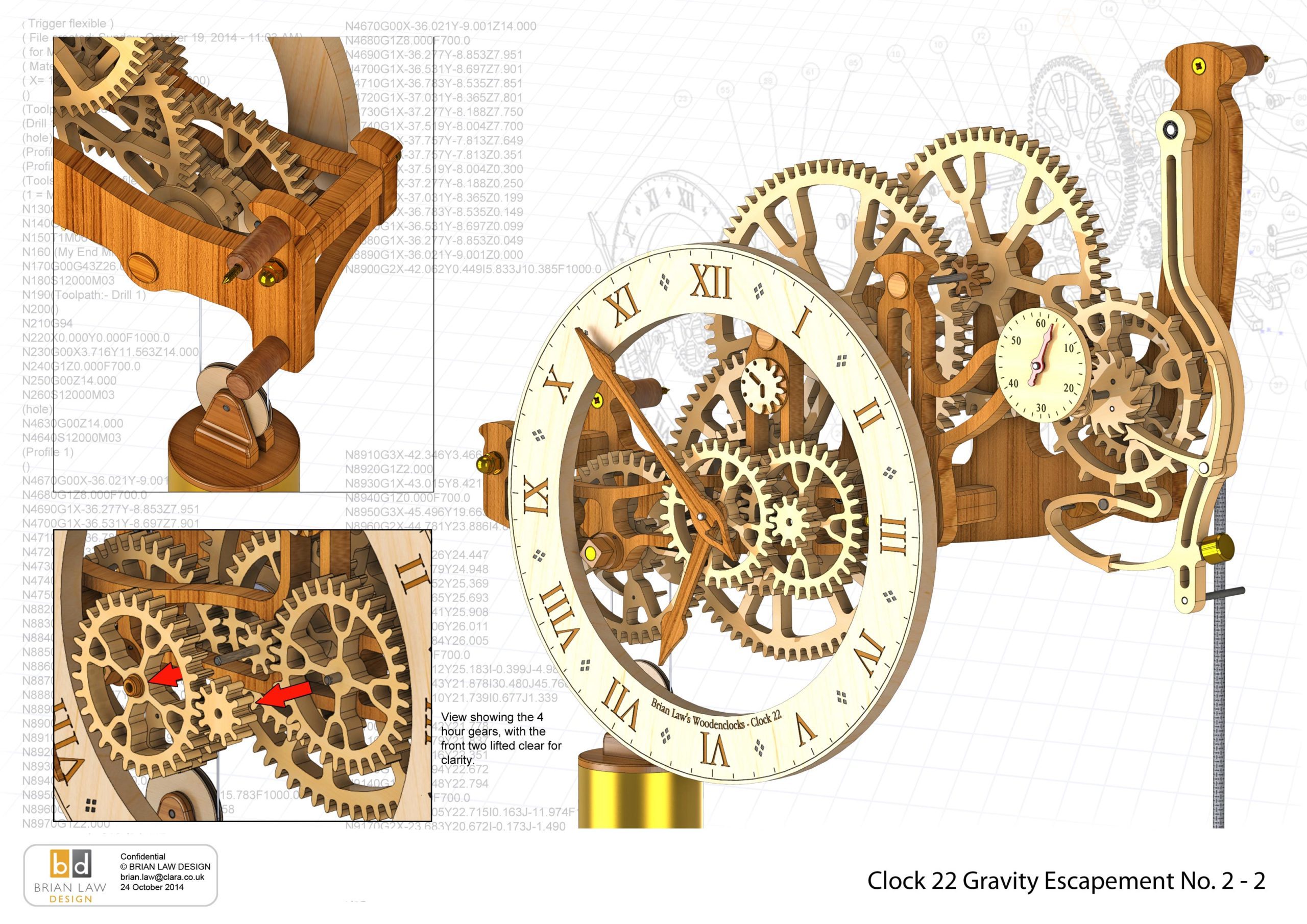
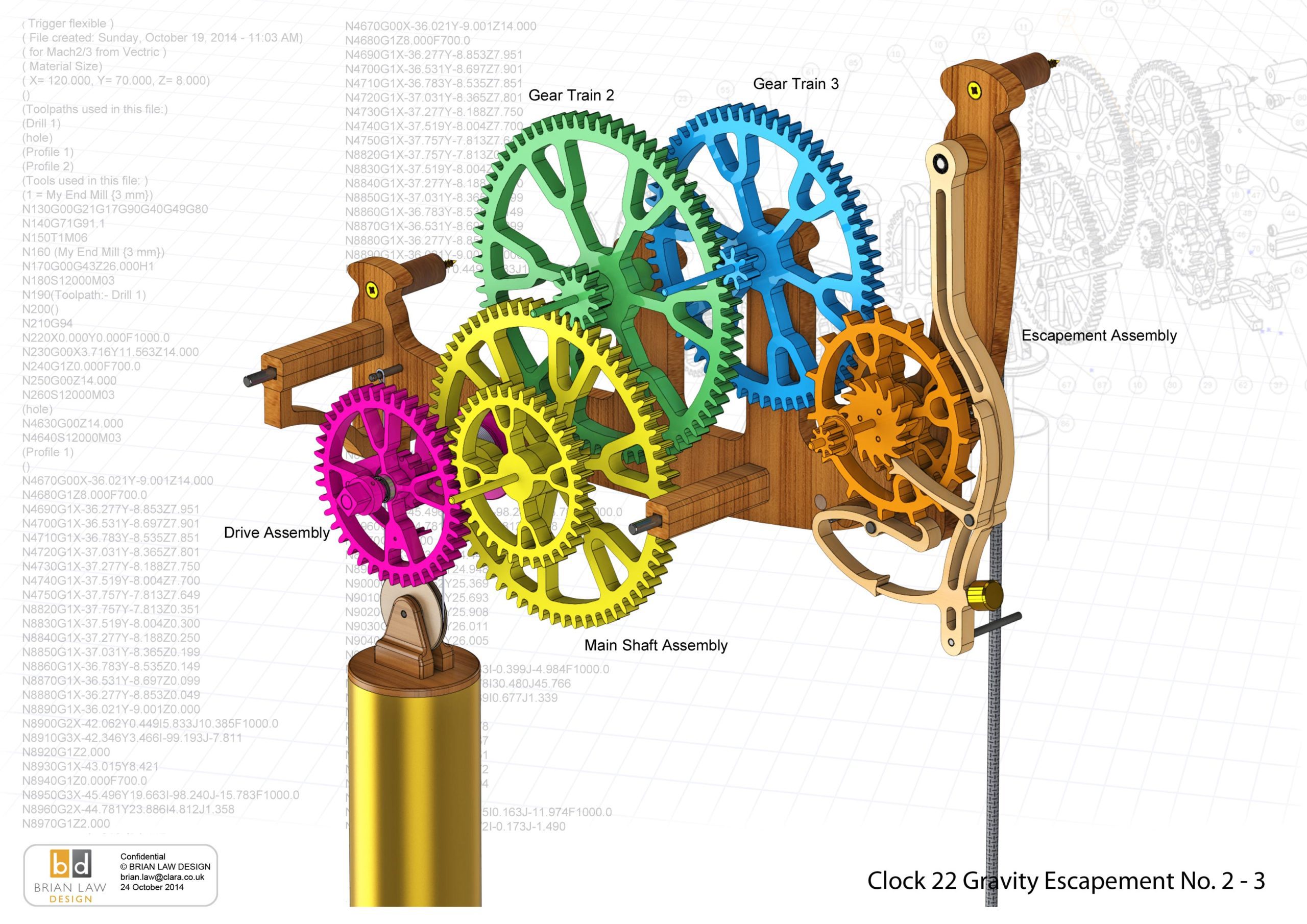
This new design has been made more compact so that all the action is at eye level when mounted on the wall at around 1500 mm from the floor, in this position
the large gears in the drive train can be seen above the clock with the escapement exposed at the side so the action is clearly visible.
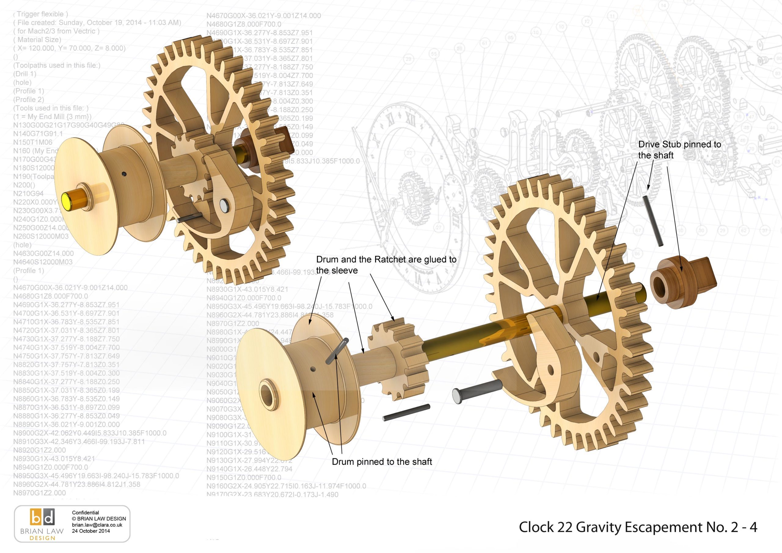
A pulley has been built into the top of the weight so that the clock will run for 24 hours on a single wind. I used 3 kg of lead to drive the clock, but I suspect some in efficiency in my gear train may have made that a little bit more than is truly necessary.
I have experimented with engraving for the dial on the prototype, not tried that before with the CNC router but it worked out quite well. I normally use Cut 2D for the generation of the machining code, but that doesn’t do engraving so I used Artcam Express for engraving the dial and worked out really well.
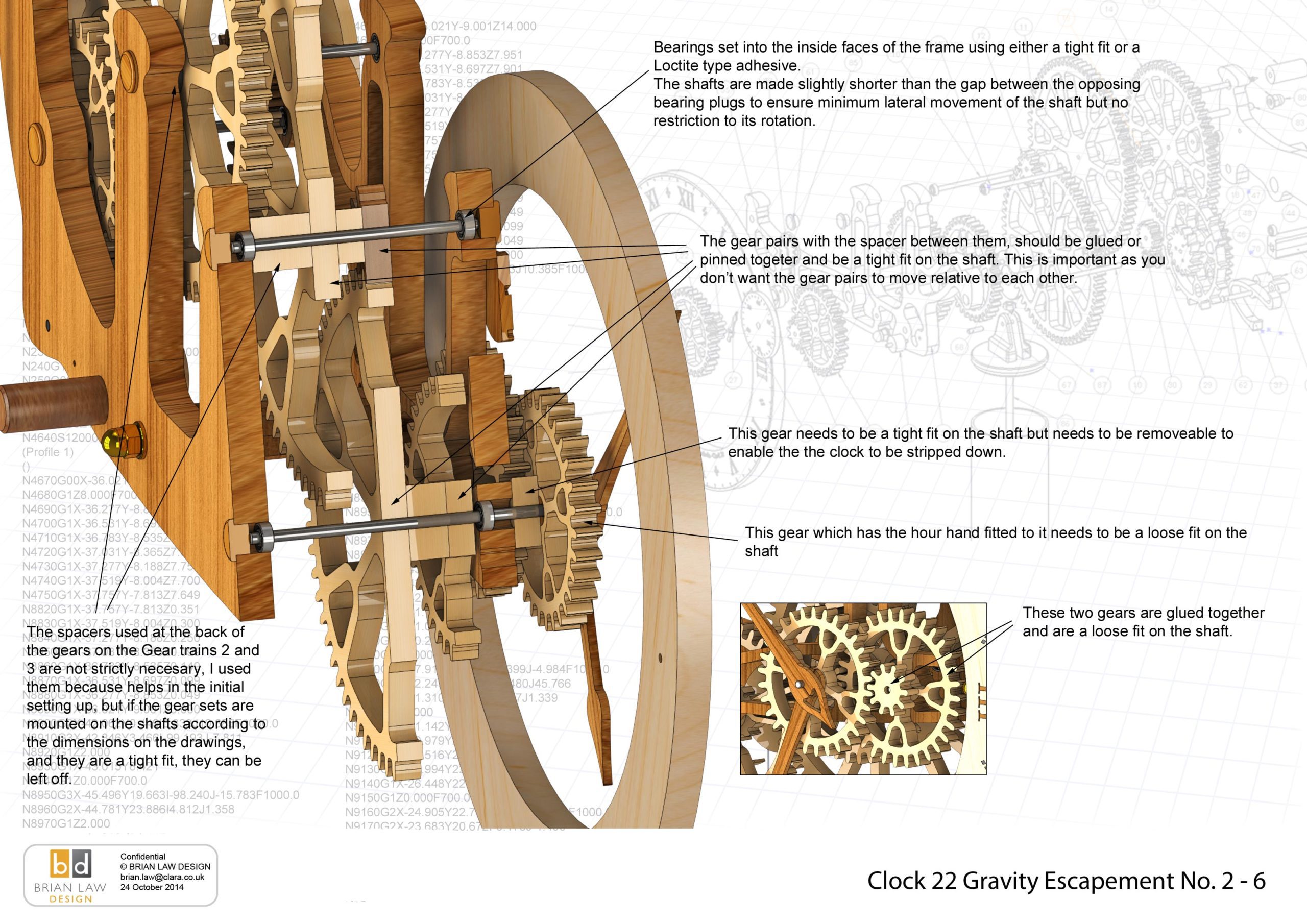
I have used miniature ball bearings to support all the shafts to reduce friction and ensure that the drive can run efficiently.
You can view the Detail drawings of the clock and the renders showing in detail the construction of the clock. The free files are restricted and are not suitable for actually making the clock with but all the drawings and renders along with the DXF and DWG files for using with CNC machining can be purchased from the download page.
DXF, DWG 2D files, and the IGS and STP files that can be used with your CNC machine can be downloaded here for $26. You also get the unrestricted version of the PDF files that can be printed at full size.
Drawings for this clock in PDF format can be downloaded here. These free files are restricted so that you can only view them on screen but not print them. Clicking here will download the PDF file directly to your browser, may take a few moments so please be patient.
To view
the assembly instructions for the clock
click here.
Details
of the materials and equipment
needed to build this clock.
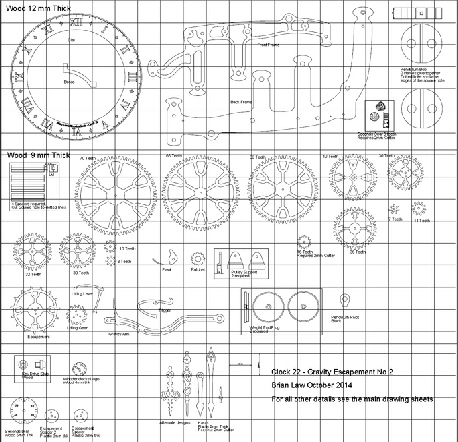
A sample from the DXF/DWG files is shown here. The actual files purchased above are included on one large sheet so that they may be directly loaded into your CAM program.
To print only a single item of the drawing to scale using Adobe Acrobat Reader, do the following:
Go to Edit, then click on Take a snapshot, move the cursor to the top left of the item you want to print and hold down the left mouse button whilst you drag a box around the item. The inside of the box turns blue and you can now go to File and then click on Print. This brings up the print dialogue, make sure Selected graphic is selected and that the Page scaling is set to None and the click on OK. As long as your printer is connected you will have printed the item at size. Do this for each item you want to cut out.