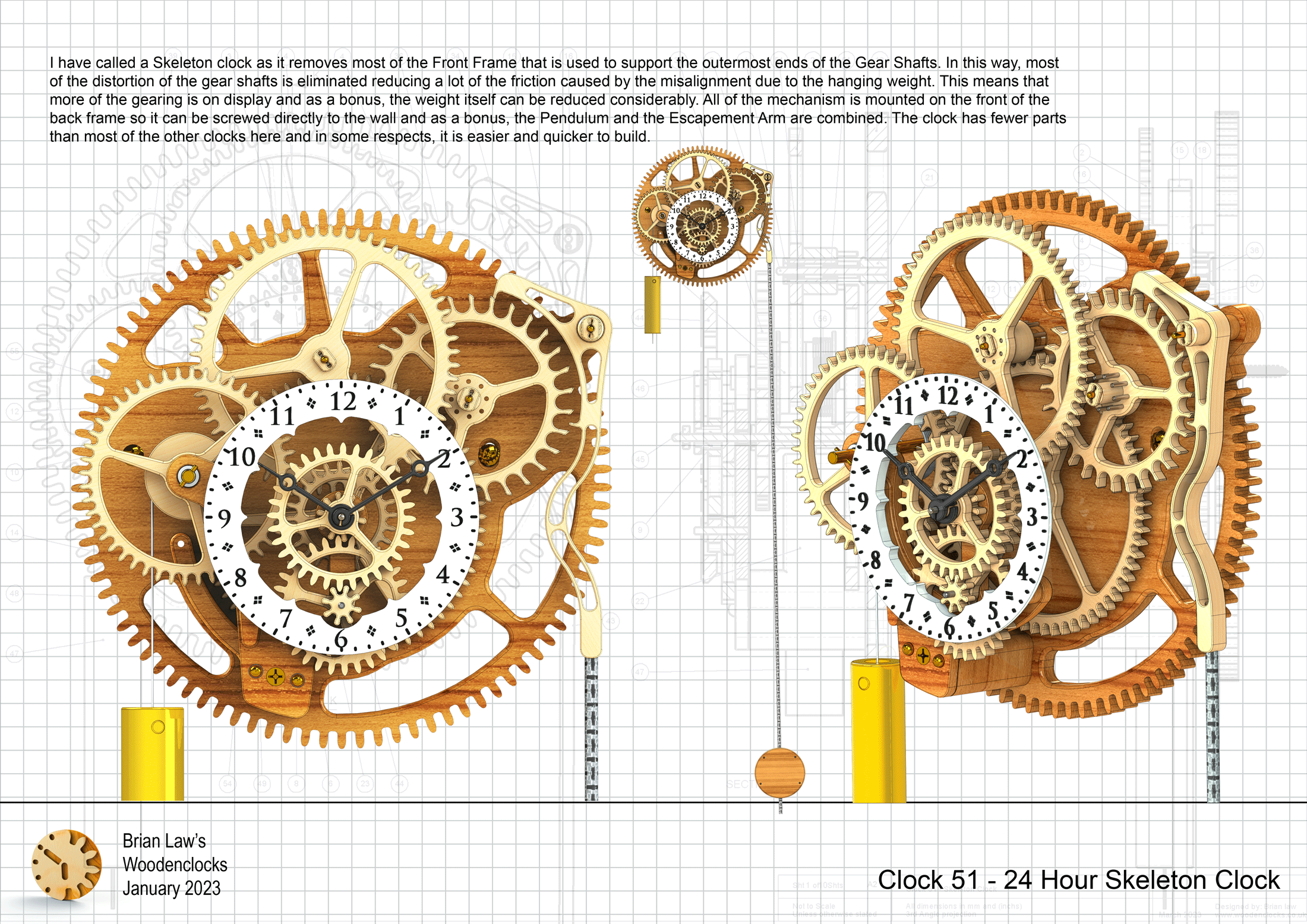
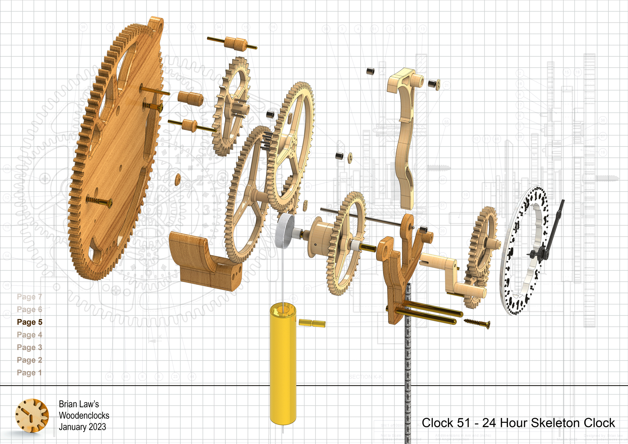
I have called this one a Skeleton clock as it removes most of the Front Frame that is used to support the outermost ends of the Gear Shafts. In this way, most of the distortion of the gear shafts is eliminated reducing a lot of the friction caused by the misalignment due to the hanging weight. This means that more of the gearing is on display and as a bonus, the weight itself can be reduced considerably. All of the mechanism is mounted on the front of the back frame so it can be screwed directly to the wall and as a bonus, the Pendulum and the Escapement Arm are combined. The clock has fewer parts than most of the other clocks here and in some respects, it is easier and quicker to build.
The clock will run for 26 hours on a single winding if the centre of the clock is hung with the dial 1.6 meters above the floor. I have had the prototype running for a couple of months now with a weight of 500 grams, but earlier experiments show that it can run with significantly smaller weights around 250 grams. All of the parts can be either CNC machined, cut out by hand or 3D printed using the files provided. I must add though that many of the round parts would be more easily made on a lathe.
STP files are also available for you to use in a suitable STP file reader so you can more easily understand how all the parts fit together, also so you can alter the design of any of the parts to suit your own ideas of what the finished clock should look like.
DXF files, and the STP and STL files that can be used with your CNC machine and 3D printer can be downloaded here for $26. You also get the unrestricted version of the PDF files that can be printed at full size and in this clock only the STL files if you need them. Also a photos of the clocks build sequence.
Drawings for this clock in PDF format can be downloaded here. These free files are low resolution and not to scale and only a sample of the full set that comes in the paid for version. Clicking here will download the PDF file directly to your browser, may take a few moments so please be patient.
A sample from the DXF file – the file is purposely low resolution, with no vector data. The actual files purchased above are included on one large sheet so that they may be directly loaded into your CAM program.
To print only a single item of the drawing to scale using Adobe Acrobat Reader, do the following:
Go to Edit, then click on Take a snapshot, move the cursor to the top left of the item you want to print and hold down the left mouse button whilst you drag a box around the item. The inside of the box turns blue and you can now go to File and then click on Print. This brings up the print dialogue, make sure Selected graphic is selected and that the Page scaling is set to None and the click on OK. As long as your printer is connected you will have printed the item at size. Do this for each item you want to cut out.