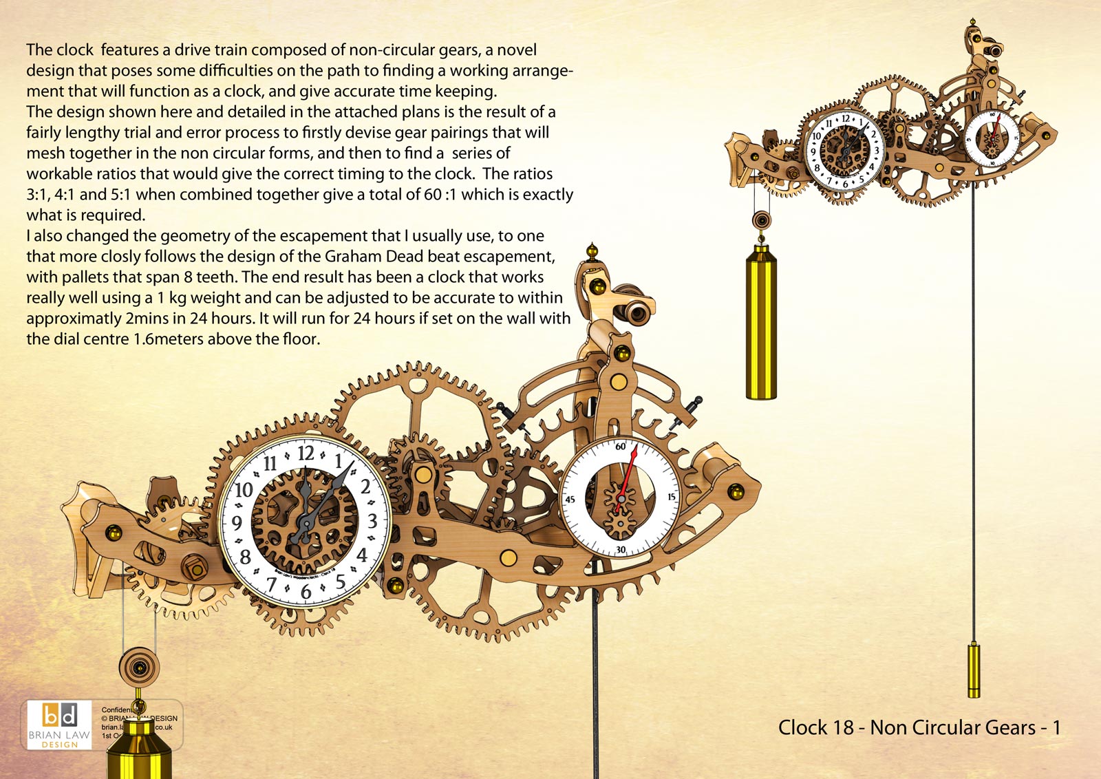
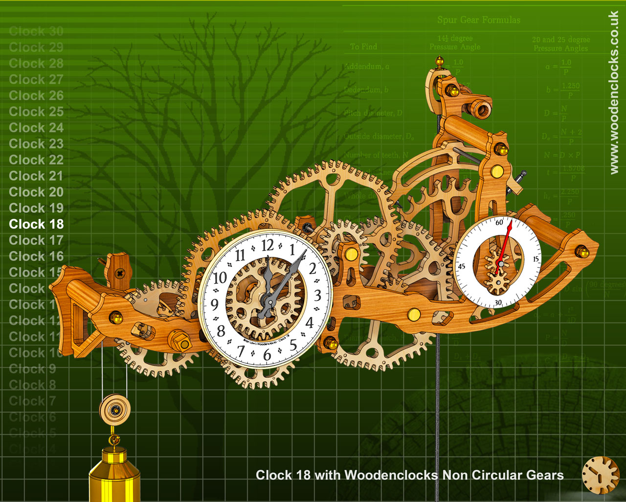
Clock 18 features a drive train composed of non-circular gears, a novel design that poses some difficulties on the path to finding a working arrangement that will function as a clock, and give accurate time keeping. The design is the result of a fairly lengthy trial and error process to firstly devise gear pairings that will mesh together in the non circular forms, and then to find a series of workable ratios that would give the correct timing to the clock. The ratios 3:1, 4:1 and 5:1 when combined together give a total of 60 :1 which is exactly what is required. I also changed the geometry of the escapement that I usually use, to one that more closely follows the design of the Graham Dead beat escapement, with pallets that span 8 teeth. The end result has been a clock that works really well using a 1 kg weight, and can be adjusted to be accurate to within approximately 2 mins in 24 hours. It will run for 24 hours if set on the wall with the dial centre 1.6 meters above the floor.
You can view the Detail drawings of the clock and the renders showing in detail the construction along with the instructions for assembly. The free files are restricted and are not suitable for actually making the clock with but all the drawings and renders along with the DXF and DWG files for using with CNC machining can be purchased from the download page.
I have used miniature ball bearings to support all the shafts to reduce friction and ensure that the spring drive can run efficiently. The bearings can be obtained from www.technobotsonline.com
DXF, DWG 2D files, and the IGS and STP files that can be used with your CNC machine can be downloaded here for $26. You also get the unrestricted version of the PDF files that can be printed at full size.
Drawings for this clock in PDF format can be downloaded here. These free files are restricted so that you can only view them on screen but not print them. Clicking here will download the PDF file directly to your browser, may take a few moments so please be patient.
To view
the assembly instructions for the clock
click here.
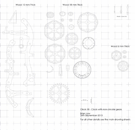
A sample from the DXF/DWG files is shown here. The actual files purchased above are included on one large sheet so that they may be directly loaded into your CAM program.
To print only a single item of the drawing to scale using Adobe Acrobat Reader, do the following:
Go to Edit, then click on Take a snapshot, move the cursor to the top left of the item you want to print and hold down the left mouse button whilst you drag a box around the item. The inside of the box turns blue and you can now go to File and then click on Print. This brings up the print dialogue, make sure Selected graphic is selected and that the Page scaling is set to None and the click on OK. As long as your printer is connected you will have printed the item at size. Do this for each item you want to cut out.